Although the layered model is one of the first things we learn when starting out with networking—and most textbooks introduce it right at the beginning—there is surprisingly little hands-on practice directly related to network layering.
It wasn’t until many years into my career that my understanding of this concept started to really become clear. In this post, I’ll share how I understand “layering.” These concepts seem simple at first, but once you combine them with real-world experience, you’ll continuously uncover deeper insights.
How are networks connected?
When we access a website, we’re essentially sending multiple HTTP requests and receiving HTTP responses. Let’s set DNS aside for now, since its purpose is to resolve names to IPs. Once we have the IP address, our communication with the server no longer involves DNS. So let’s assume we already know the website’s IP—how does the request actually get sent from our laptop to the website?
At the physical level, the packet travels from our computer to the router, then from the router to the ISP. Inside the ISP’s network, it passes through many routers and switches before finally reaching the server. This entire forwarding chain can be seen as a sequence of point-to-point transmissions between devices. Every time a packet is forwarded, it happens between two devices (even broadcasts can be seen as repeated transmissions between two devices). So, we can focus on what happens to a packet during these point-to-point transfers.

The diagram is simplified, retaining only the most important address information from each layer.
When Layer 2 forwarding takes place—for example, when the laptop sends data to the router—the source MAC address is set to the laptop’s MAC, and the destination MAC address is set to the router’s MAC.
Layer 2 doesn’t look at anything in Layer 3 or above. So from its perspective, the packet looks something like this: the IP address and other Layer 3 info are just data payload.

Setting the MAC address when sending data from a computer to a router might seem unnecessary. After all, in this kind of point-to-point network, even without an address, the data wouldn’t go to the wrong place. In fact, there are some Layer 2 technologies, like Frame Relay, where Layer 2 headers don’t include MAC addresses (though they have something with a similar function).
But in the following structure, MAC addresses become very useful. For example, when Computer 1 wants to send data to Computer 2, it sets the destination MAC address to MAC 2 and hands the packet off to the switch. The switch then forwards it to Computer 2. Without MAC addresses, the switch wouldn’t know whether to send the packet to Computer 2 or Computer 3.
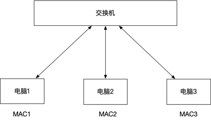
With MAC addresses, the switch can forward the packet out through the port associated with the destination MAC address.
Most modern switches are quite “intelligent”—they can forward packets by looking up the corresponding port in a MAC address table. But switches from forty years ago weren’t so smart. When a packet came in through one port, they would simply forward it to all other ports. These were called hubs. All hosts on the network would receive the packet, but only the one whose MAC address matched would process it; the others would discard it.
Ethernet itself was designed for broadcast-based transmission, where every packet was sent to all devices on the network. That’s why early Ethernet included features like collision detection. These mechanisms are rarely used today, as the technology has evolved.
Layer 3 forwarding follows the same principle—it only cares about Layer 3 information, with IP addresses being the most important. When a router receives a packet, it examines the destination IP address and uses its routing table to determine which interface to forward it through. Routers typically have multiple interfaces connecting different networks (for example, a home router has one interface connected to the local network and another connected to the ISP).
You can think of the routing table as a database that tells the router: “Given a destination IP, which physical interface should I use to send this packet?” Once the proper interface is determined, the router sends the packet out through that interface.
At this point, the Layer 2 network becomes the carrier for Layer 3. It doesn’t matter what Layer 2 technology is used—as long as it can deliver the encapsulated Layer 3 packet to the next hop. It could be Ethernet, Wi-Fi, Frame Relay, etc.
If Ethernet is used, the router wraps the Layer 3 packet with a Layer 2 header: setting the destination MAC to the next hop device and the source MAC to its own. The packet is then transmitted via the physical layer.
All upper-layer protocols rely on the IP protocol to transmit their data—whether it’s TCP, UDP, ICMP, or others, they all use IP as their transport medium.
To access websites across the globe (or from a networking perspective, remote servers and devices), our computers need to connect—hop by hop—with devices all over the world. These connections are usually physical: submarine fiber cables, ATM lines, twisted pairs, copper wires, etc. Wireless technologies are mostly used at the access layer due to their lower signal-to-noise ratio. It’s rare to see wireless links between backbone forwarding devices—they’re almost always connected by physical cables.
This is why when someone jokes online, “I’m going to crawl through the Ethernet cable and strangle you,” it’s technically plausible: if you could actually crawl through the wires, you could reach any device anywhere in the world.
For all devices to communicate with each other, they must speak a common protocol—this shared “language” is IP. Many upper-layer protocols run over IP, and IP can be encapsulated by many different lower-layer technologies. But IP is the indispensable middle layer.
Within a single autonomous system (AS), it’s possible to use non-IP protocols (though I’ve never actually seen this in practice), but communication between autonomous systems always relies on IP. Routing information between networks is exchanged using BGP (Border Gateway Protocol), which also operates over IP.
This structure resembles an hourglass: diverse protocols at the top and bottom, but all data funnels through the IP layer in the center.
Devices at Different Network Layers
All forwarding between two devices in a network must pass through the physical layer. The physical layer performs relatively simple tasks. For instance, a hub is a physical layer device. It’s classified as such because it doesn’t even inspect Layer 2 (or higher) information—it treats everything above the physical layer as opaque data. When a hub receives data on one port, it blindly copies and transmits it out through all other ports—like a “port repeater.”
Layer 2 devices forward packets based on MAC addresses. They don’t modify the packet content. You might have wondered in the previous examples: how does a switch know which port corresponds to MAC2, in order to send the packet there?
The answer is simple—if the switch doesn’t know, it sends the packet out through all ports (except the one it was received on). This is different from a hub, though. While a switch may not initially know the MAC-to-port mapping, it has the ability to learn.
This learning happens by examining incoming packets. For instance, if a packet arrives on port 1 with a source MAC of MAC1, the switch will remember that MAC1 is reachable via port 1. This process is called MAC address learning, and the result is a MAC address table, which is stored in memory. Next time the switch needs to send a packet to MAC1, it can send it directly to port 1 instead of broadcasting.
Layer 3 devices forward based on IP addresses, and their job is heavier than that of Layer 2 devices. Unlike Layer 2 switches, routers cannot “learn” routing paths from the packets themselves—because the sender doesn’t know how to reach the destination IP and relies on the router to figure that out.
Routers consult their routing table to determine the next hop. This table can be manually configured (static routing). For example:
- Packets to subnet XX go through interface 1
- Packets to subnet YY go through interface 2
- If there’s no match, send via interface 3 (default route)
However, in data centers with thousands of devices, manual configuration is impractical. Routing tables are usually built dynamically. Each router is aware of its directly connected networks and shares that information with other routers using routing protocols. This way, all routers collaboratively build a global forwarding map.
The details of routing protocols are complex and beyond this explanation, but in essence, Layer 3 devices exchange two kinds of information:
- Control plane: routing information, i.e., how to get to different destinations
- Data plane: actual data that needs to be forwarded
In this section, I’ve referred to “Layer 2 devices” and “Layer 3 devices” rather than “switches” and “routers” because in modern networks, the distinction is no longer clear-cut. Many switches can also perform Layer 3 forwarding.
Take a typical home router, for instance—it’s actually a switch + router + NAT + firewall combined in one device.
While “router” might sound more advanced than “switch,” that’s not always the case. In data centers, some switches are extremely powerful—more expensive and more capable than many routers. These high-end switches support hundreds of ports at line speed and play a vital role in network infrastructure.
Network Protocols and Layered Architecture
There’s one last puzzle piece to complete the picture from earlier: The computer knows how to encapsulate data at Layer 3 by adding the IP header, but before sending it out, it also needs to encapsulate it at Layer 2. The router’s IP is either manually configured or obtained via DHCP—but how does the computer know the router’s MAC address (i.e., the destination MAC)?
Let’s use an analogy: you walk into a new classroom and need to find a student named Xiao Ming Li. What do you do? You shout, “Who’s Xiao Ming Li?”
The same idea applies in networking. When the sender doesn’t know the MAC address corresponding to a known IP address, it broadcasts to the entire network:
“Who has this IP address? If it’s you, please reply. My MAC address is MAC1.”
The router responds, “That’s me,” and sends a reply with its own MAC address in the source field.
So, What Layer Does ARP Belong To? Most sources say ARP is a Layer 2 protocol. Some say it lies between Layer 2 and Layer 3.
In reality, this debate is a bit misguided. That’s because it mixes two different perspectives:
- Which layer the protocol is implemented on (i.e., what it depends on)
- Which layer the protocol provides service for
If we separate these two, everything becomes clearer. ARP is implemented over Layer 2 (it only uses Layer 2 functions, no need for IP), and it serves Layer 3, helping find the MAC address corresponding to an IP address.
We can use the same logic to categorize other often-debated protocols:
- TLS is built on Layer 4 (TCP) and serves the Application Layer
- TCP is built on Layer 3 (IP) and serves the Application Layer
- ICMP operates at Layer 3 and serves Layer 3
- EIGRP and OSPF are built on IP and serve Layer 3
- BGP is built on Layer 4 (TCP) and serves Layer 3
(Yes, it’s a bit of a twist: BGP uses TCP to exchange Layer 3 routing information)
This perspective provides a more practical and flexible way of understanding protocol layering—focused not on rigid boundaries, but on function and dependency.
Why Do We Use Layering?
My understanding is: to allow each protocol to handle a part of the problem, and to enable different protocols to work together. For example, the IP protocol only needs a Layer 2 protocol to help forward packets—any Layer 2 protocol will do. This way, when Wi-Fi becomes widespread or 2G upgrades to 3G or 4G, we can continue using the IP protocol without having to update or replace it. It’s like how a company is divided into departments, each responsible for a specific function. As long as each department does its job well, how they operate internally doesn’t concern the others.
Each protocol makes its own promise: for example, the Layer 3 protocol promises to do its best to ensure that packets reach their destination. Layer 4 promises the application layer that the data it transmits will not be lost, corrupted, or out of order. So when we write application-layer code, we never have to worry about issues like out-of-order data or packet loss.
Relying on the promises made by lower-layer protocols saves a lot of effort. It’s a bit like how we use libraries for string processing in programming instead of writing everything from scratch.
Understanding Protocols
As users, when we use these protocols, we need to understand what functions they provide and what requirements they impose—similar to reading documentation before using a third-party library.
With this mindset, many so-called problems cease to be problems at all. For example, the “packet sticking” issue is often criticized as a poor interview question. It typically asks, “If multiple packets are sent over TCP and get stuck together, making them indistinguishable, what do you do?” But this question shows the interviewer doesn’t really understand TCP. TCP is specifically designed to help users send a stream of bytes—it doesn’t have the concept of “packets” at all. All data is meant to be “stuck together” during transmission. This isn’t a flaw; it’s a fundamental feature of TCP. If you choose to use TCP, then you need to design your own protocol on top of it that can be interpreted as a stream. For instance, the HTTP protocol uses \r\n\r\n to separate the Header and Body, and then relies on the Content-Length value in the Header to determine how much data to read for the Body. Similarly, the Redis protocol typically starts with a number indicating the content length; once that amount is read, the next chunk can be interpreted as the next request.
Here’s another example—a common misunderstanding of the HTTP protocol. As users (and even developers), we often think: a GET request only requires a URL, while a POST request requires a URL and a body. The URL is visible in the browser’s address bar, but the body is not, leading some to assume that POST is more secure than GET. However, if you capture and inspect the packets, you’ll see that both GET and POST methods transmit the same data structure. The only difference between them is one field—the method itself. So if an interviewer asks: “What’s the difference between GET and POST?”, I believe that, structurally, aside from the method field, there’s no real difference:
- GET can also carry a body;
- POST can also include URL parameters;
- POST is not inherently more secure than GET—the body is just as exposed when captured with packet-sniffing tools.
The Importance of Network Layering in Troubleshooting
In real-world work scenarios, network layering plays a crucial role when troubleshooting issues.
From the earlier discussion, we can draw a key conclusion: if a certain layer encounters a problem, all the protocols built on top of that layer will also experience issues—because higher-layer protocols rely on the lower layers to function.
For instance, if you can’t connect to a database, the first step might be running:
nc -v 10.0.0.1 3306If the connection fails, it means the TCP layer has a problem. You can then try:
ping 10.0.0.1If this succeeds, then Layer 3 (IP layer) is functioning properly, and there’s no need to investigate ARP or routing—those are already proven to be working. A reachable Layer 3 but unreachable Layer 4 clearly points to an issue at Layer 4—possibly a firewall blocking the port. On the other hand, if ping fails, then you need to investigate Layer 3 and below—is ARP functioning? Is routing correct? And so on.
Likewise, if your nc test succeeds, then Layers 4 and below are fine, and you can shift your focus upward—maybe the database process is stuck.
When it comes to describing issues, the layered model also helps foster clearer communication with colleagues. For example, instead of vaguely saying, “Please check if the database is having issues,”—which might not be actionable for a DBA who doesn’t have access to your environment—you could be more precise and say, “We’re unable to connect to 10.0.0.1 on port 3306, but we can ping the IP.” That instantly narrows the scope and allows others to start troubleshooting efficiently.
In practice, no one tells you in advance which layer the problem lies in. Real-world troubleshooting isn’t a test—you need to understand the responsibility of each layer in order to find clues and correctly determine which layer to focus on based on observed behavior.
Note: The post is authorized to republish and translated from https://www.kawabangga.com/posts/6295

this is awesome post