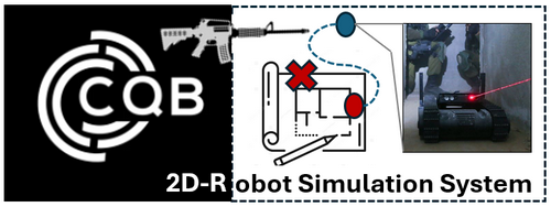
Program Design Purpose: The integration of robots in Close Quarters Battle (CQB) represents a significant advancement in modern military and law enforcement tactics. These robots, designed to navigate tight spaces, gather real-time intelligence, and engage threats, are invaluable assets in high-stakes scenarios. Our goal is to develop a 2D tactical board simulation system, similar to a computer game, that can load building floor blueprints, display CQB squad (robot) positions, enemy locations, and simulate CQB robot enemy search progress in the real world. This program will allow users (attack squad) to plan CQB robot enemy searching strategies and improve robot's enemy prediction within a controlled environment.
The main user interface of the simulation system is shown below:
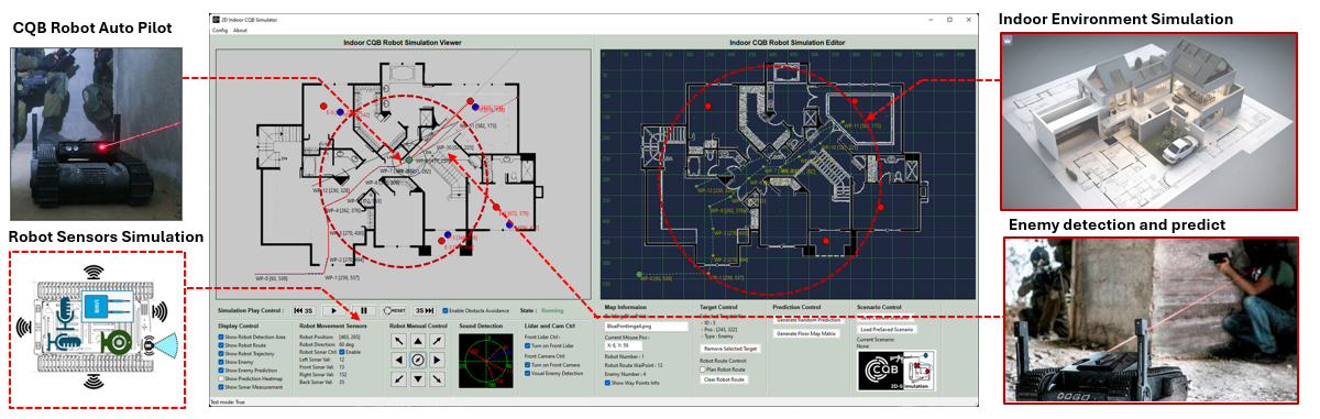
Figure-00: 2D_Indoor_CQB_Robot_Simulation System Overview Diagram, version v0.1.2 (2024)
# Created:     2024/07/30
# Version:     v_0.1.2
# Copyright:   Copyright (c) 2024 LiuYuancheng
# License:     MIT License
Introduction
Robots are employed in Close Quarters Battle (CQB) to minimize the risks faced by human soldiers and officers by handling the most hazardous tasks. Equipped with advanced sensors, cameras, and communication systems, CQB robots provide operators with a comprehensive understanding of their environment. Their ability to navigate narrow corridors, stairwells, and cluttered rooms makes them ideal for urban combat and building searches. By relaying live video and audio feeds back to the control center, these robots enable real-time decision-making and seamless coordination with attack squads.
The 2D Indoor CQB Robot Simulation program is a simulation tool designed to configure various CQB scenarios, aiding in the improvement of the robot's autopilot, enemy search, and prediction algorithms. The program consists of two main components: the CQB Scenario Tactical Board Editor and the Situation Simulation Viewer. The Tactical Board Editor allows users to create and configure CQB scenarios, while the Situation Simulation Viewer simulates how the CQB robot utilizes its sensors for environmental visualization, enemy search, and prediction in real-world situations. The program main UI is shown below:
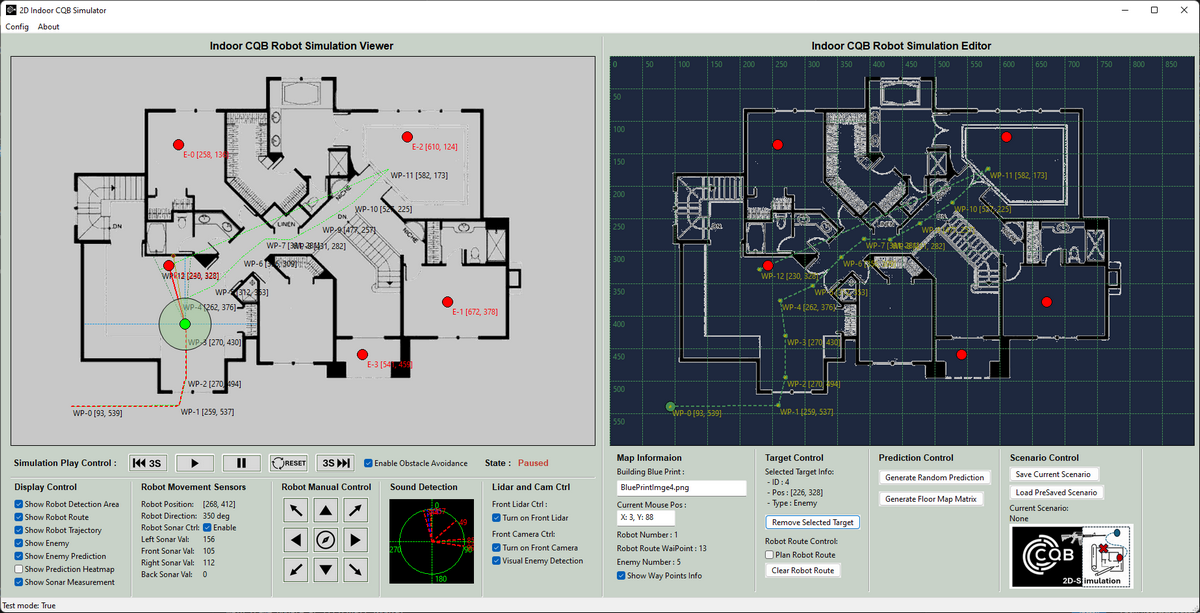
Figure-01: Program UI screen shot, version v0.1.2 (2024)
CQB Scenario Tactical Board Editor Introduction
The CQB Scenario Tactical Board Editor allows users to create and configure CQB scenarios with the following steps:
-
Step 1: Load the building's indoor blueprint into the editor to generate the floor map matrix.
-
Step 2: Set the robot's starting position, then define its autopilot route and enemy search path.
-
Step 3: Adjust the robot's motion and detection parameters, such as movement speed, sensor sensitivity, and detection range.
-
Step 4: Place enemies within the scenario and define their movement strategy (e.g., stationary, patrolling, or random wandering).
After finished configuring a CQB scenario, users can save the scenario to a file for future use, allowing them to load and modify it as needed.
CQB Situation Simulation Viewer Introduction
The Situation Simulation Viewer replicates real-world conditions as the robot follows the defined enemy search path. The viewer supports both autonomous robot operation and manual control, enabling users to simulate different operational scenarios. It generates real-time sensor data based on the floor blueprint and enemy configuration, such as:
-
Sonar detecting wall reflections to calculate the distance between the robot and the building walls.
-
Front LIDAR identifying obstacles like glass doors and furniture that the robot cannot pass.
-
A 360-degree microphones array pinpointing potential enemy positions based on sound.
-
Electro-optical cameras detecting enemies behind glass doors through visual analysis.
The viewer also visualizes the robot's enemy prediction results. During the simulation, users can step forward or backward through the scenario to refine the enemy search path and improve the robot's performance.
Use Case and Future Work
Project Demo Video
To use the system, please follow the below video:
| Idx | Time Stamp | Description |
|---|---|---|
| 1 | 0:04 / 5:09 | Load building flow print image |
| 2 | 0:19 / 5:09 | Set CQB robot autopilot route path |
| 3 | 0:46 / 5:09 | Plan CQB scenario enemies' position |
| 4 | 1:10 / 5:09 | Check enemy information and remove unneeded enemy |
| 5 | 1:27 / 5:09 | Finish scenario editing and save to file |
| 6 | 2:09 / 5:09 | Start CQB scenario simulation |
| 7 | 2:12 / 5:09 | Visual and lidar enemy detection |
| 8 | 2:39 / 5:09 | Simulation play forward and backward control |
| 9 | 3:27 / 5:09 | Robot movement manual control |
| 10 | 3:36 / 5:09 | Return to autopilot route path |
| 11 | 3:49 / 5:09 | Real time enemy sound detection |
| 12 | 4:08 / 5:09 | Visual and lidar enemy detection |
| 13 | 4:22 / 5:09 | Enemy position prediction |
| 14 | 4:58 / 5:09 | Enemy heatmap generation |
System Design
The program consists of several subsystems, each with key features that contribute to the overall simulation. This section introduces and details the design of these subsystems, including the CQB environment simulation, CQB robot sensor simulation, enemy detection, and prediction algorithm design.
CQB Environment Simulation Design
Before simulating the CQB robot's operations, it is essential to accurately build the environment from the building's floor blueprint. This enables the robot's sensors to "interact" with the environment as they would in the real world. This section explains how we construct the environment using the building blueprint and convert it into a map matrix through image visualization analysis. There are three main steps involved in this process:
Step 1: Establish the Floor Blueprint Coordinate System Using UWB Position Amplifiers
Typically, the attack squad deploys three UWB (Ultra-Wideband) position amplifiers in a right-angled triangle configuration to cover the building area. We set the positions of these three UWB amplifiers as the origin (0,0), (max(x), 0), and (0, max(y)) of our blueprint matrix map. By scaling the loaded blueprint image to fit within this coordinate system, we ensure that the robot's location identification and the building environment are aligned within the same 2D coordinate system. The steps workflow is shown below:
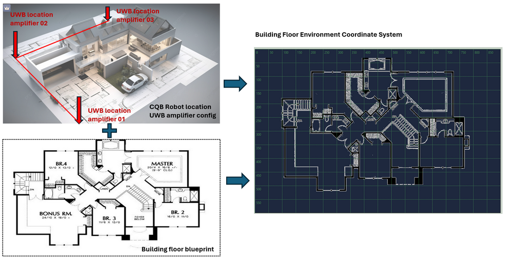
Figure-02: Establish the Floor Blueprint Coordinate System, version v0.1.2 (2024)
This alignment allows for precise interaction between the robot's sensors and the simulated environment.
Step 2: Construct the Indoor Environment Map Matrix
Once the blueprint is correctly positioned and scaled within the coordinate system, we use computer vision (CV) techniques to convert the floor blueprint into a 2D matrix for simulation purposes, as illustrated below:
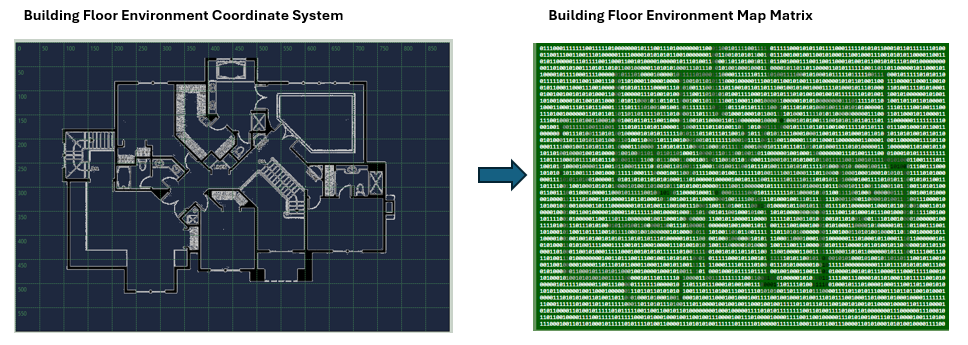
Figure-03: Construct the Indoor Environment Map Matrix, version v0.1.2 (2024)
In this 2D matrix, different numerical values represent various materials or spaces within the environment (with material values ranging from 1 to 255). For example:
-
An empty space, where the robot can move freely, is represented by the value
0. -
A glass door, which sonar sensors cannot penetrate but LIDAR and cameras can, is represented by the value
10. -
A furniture which LIDAR can scan its shape and the sound can pass thought is represented by the value
100. -
A wall, which blocks all sensors and sound, is assigned the value
255.
This matrix format enables the simulation to distinguish between different types of obstacles and open areas, allowing for accurate robot-environment interaction.
Step 3: Simulate Robot and Environment Interaction
After constructing the environment matrix, we develop an interaction module that simulates how the robot's sensors interact with the environment, mimicking real-world scenarios. An example of this interaction is shown below:
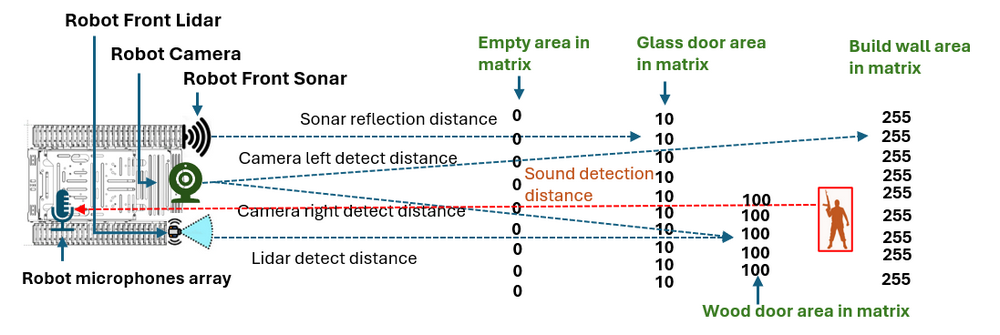
Figure-04: Simulate Robot and Environment Interaction, version v0.1.2 (2024)
When the robot encounters different elements like glass doors, wooden furniture, or walls, the interaction manager module traces the sensor’s detection line from the robot's position, checking the material values in the matrix along the sensor's path. The detection continues until it encounters a material value that the sensor cannot penetrate, based on its settings. For instance:
-
Movement sound sensors stop detecting when they reach a glass door (material value =
10). -
Camera and LIDAR sensors can see through the glass door (material value =
10) but are blocked by wooden furniture (material value =100). -
Sound detection sensors can penetrate wooden doors (material value =
100) but are halted by building walls (material value =255).
This system allows for detailed and realistic simulation of sensor interactions, critical for testing and refining CQB robot strategies.
CQB Robot Sensor Simulation Design
The sensor system in Close Quarters Battle (CQB) robots is critical for navigating, detecting threats, and providing real-time intelligence in confined and potentially hostile environments. Typically, a CQB robot is equipped with eight types of sensors: Optical Sensors, Thermal Imaging Sensors, Proximity and Obstacle Detection Sensors, Environmental Sensors, Audio Sensors, Motion and Vibration Sensors, Communication and Signal Sensors and Multispectral and Hyperspectral Sensors. These sensors enable the robot to map the environment, identify potential dangers, and make informed decisions.
In our system, we simulate five key types of sensors used on the robot, as shown below:
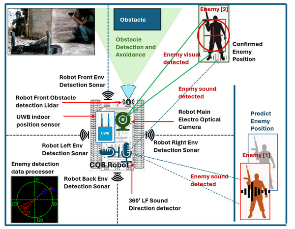
Figure-05: CQB Robot Sensor Simulation, version v0.1.2 (2024)
| Sensors Name | Sensor Type | Description |
|---|---|---|
| Electro Optical Camera | Optical Sensors | Capture detailed visual data for navigation, threat identification, and situational awareness. |
| UWB Indoor Position Sensor | Motion and Vibration Sensors | Ultra-Wideband (UWB) positioning sensor that allows the robot to determine its location within the building. |
| Environment Sonars | Environmental Sensors | Four sonars positioned around the robot (front, left, right, back) detect environmental features, such as the distance between the robot and surrounding walls. |
| 360' LF Sound Direction Detector | Audio Sensors | An array of low-frequency sound microphones that capture ambient sounds and determine the general direction of sound sources, such as footsteps, voices, or machinery noises. This audio data helps identify potential threats or locate individuals in nearby rooms or behind obstacles. |
| Front LIDAR (Light Detection and Ranging) | Proximity and Obstacle Detection Sensors | Measures distances by illuminating the target with laser light and measuring the reflection. LIDAR creates a 3D map of the environment, helping the robot navigate through tight spaces and avoid obstacles. |
The usage and display of these sensors in the 2D scenario viewer are illustrated below:
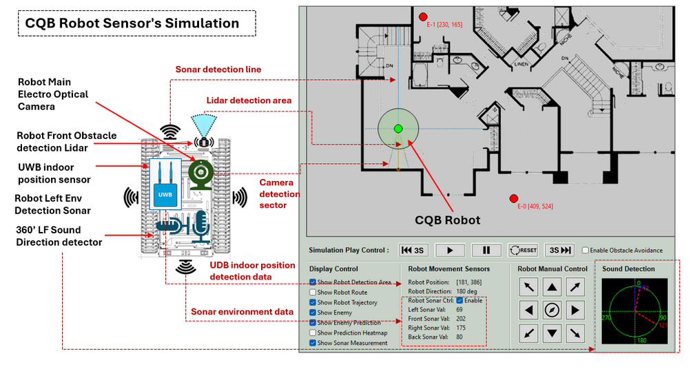
Figure-05: CQB Robot sensor and program mapping, version v0.1.2 (2024)
The robot's enemy detection data processor integrates information from multiple sensors to form a comprehensive understanding of the environment. This processor analyzes sensor fusion data, providing the robot control team with both confirmed and predicted enemy positions, enhancing the accuracy of combine visual recognition and decision-making.
Design of enemy detection and the prediction
Our system simulates the process of enemy detection and prediction during the robot enemy searching progress.
Detection Enemy Position
To detect enemy positions on the map matrix, we utilize the camera and LIDAR sensors. The camera continuously scans the area in front of the robot to identify any enemy pixels. Once the camera detects an enemy, it sends the direction data to the detection data processor module. Since the camera cannot measure distance, the processor then instructs the LIDAR to scan in that direction to determine the distance to the detected object (enemy). Using the robot's own position, enemy direction, and distance data, the processor calculates the enemy's precise location on the map.
The workflow for enemy detection is illustrated below:
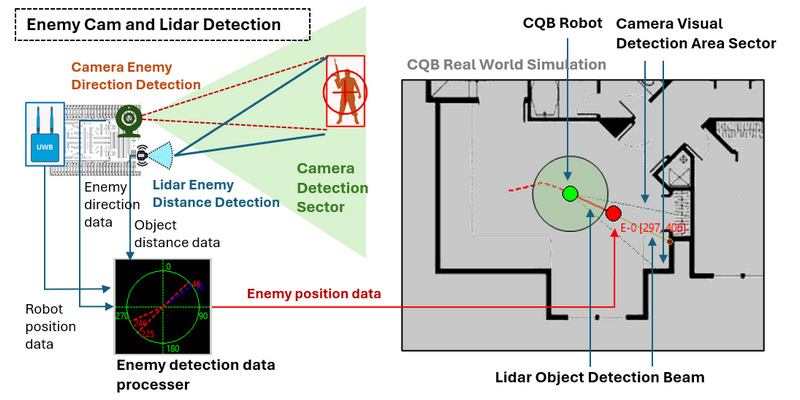
Figure-06: Detection Enemy Position with Camera and Lidar, version v0.1.2 (2024)
Predict Enemy Position
To predict the enemy’s position, we use the 360° low-frequency sound microphone array. This audio sensor captures the direction of the sound source. As the robot moves, the system records its trajectory and, combined with the sound source direction data, the enemy data processor estimates the enemy's approximate position, even if they are behind obstacles.
The enemy prediction workflow is shown below:
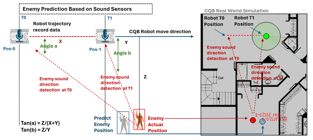
Figure-07: Predict Enemy Position with sound sensor, version v0.1.2 (2024)
During the prediction calculation process, we have the robot's trajectory distance (X) from Time-T0 to Time-T1, the enemy sound direction angle (a) at Time-T0 relative to the robot's position (Pos-0), and the enemy sound direction angle (b) at Time-T1 relative to the robot's position (Pos-1).
tan(a) = Z/(X+Y)
tan(b) = Z/Y
Using these equations, we calculate distances Y and Z. With the data from Pos-1, we can determine the enemy’s predicted position.
System Setup
Development Environment
-
python 3.7.2rc2+ 64bit [ Windows11 ]
Additional Lib/Software Need
-
wxPython : https://wxpython.org/index.html , install :
pip install wxPython -
Pillow Python Imaging Library : https://pypi.org/project/pillow/, install :
pip install pillow -
OpenCV : https://opencv.org/get-started/, install:
pip install opencv-python
Hardware Needed : None
Program Files List
| Folder | Program File | Execution Env | Description |
|---|---|---|---|
| src/floorBluePrint | *.png, *.jpg, *.bmp | All the floor blue print image files example. | |
| src/heatmap | *.png | The enemy predication possibility transparent heat map image file. | |
| src/img | *.png | The image file used by the program. | |
| src/lib | ConfigLoader.py | python 3.7 | Configuration file read and write library module. |
| src/lib | Log.py | python 3.7 | Customized log recording library module. |
| src/scenario | *.json | JSON | Scenario record files. |
| src | 2DCQBSimuRun.py | python 3.7 | The 2D CQB robot simulation program main execution program. |
| src | Config_template.txt | The program configure file template | |
| src | cqbSimuGlobal.py | python 3.7 | Module to set constants, global parameters which will be used in the other modules. |
| src | cqbSimuMapMgr.py | python 3.7 | UI map component management module. |
| src | cqbSimuMapPanel.py | python 3.7 | This module is used to create different map panel to show the simulation viewer and scenario editor. |
| src | cqbSimuPanel.py | python 3.7 | This module is used to create different function panels which can handle user's interaction (such as parameters adjustment) for the CQB robot simulation program. |
Program Execution and Usage
This section explains how to execute and use the program.
Program Execution
Before running the program, the user needs to set up the configuration file. Start by renaming Config_template.txt to Config.txt, then follow the comments within the file to set the required parameters, as shown in the example below:
# This is the config file template for the module <2DCQBSimuRun.py>
# Setup the paramter with below format (every line follow <key>:<val> format, the
# key can not be changed):
#-----------------------------------------------------------------------------
# Test mode:
TEST_MD:True
# Init the building floor blue print directory
BP_DIR:floorBluePrint
# Init the prediction heat map directory
HM_DIR:heatmap
TEST_HM:transparent_image.png
# Scenario file directory
SC_DIR:scenario
# Flag to scale the image or not
SCALE_IMG:False
Once the configuration is complete, you can run the program by either double-clicking runApp.bat or navigating to the src folder and executing the program via the command line:
python 2DCQBSimuRun.py
The program's start UI will appear as shown below:
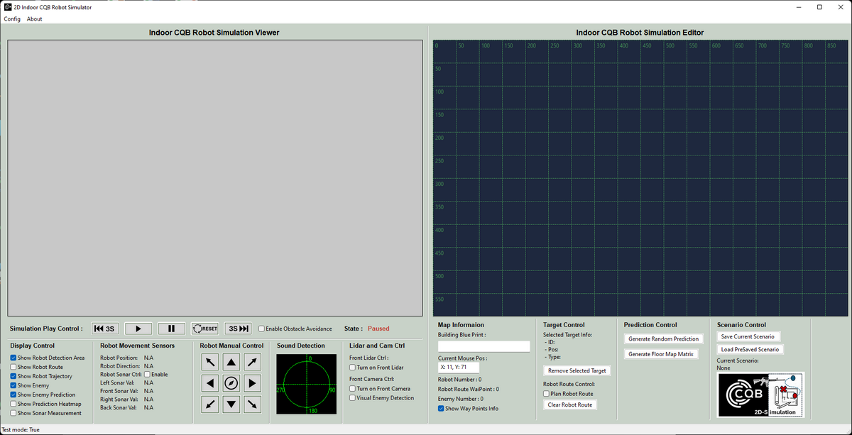
Figure-08: Program init UI screen shot , version v0.1.2 (2024)
Program Usage
After launching the program, the user interface will appear as described in the introduction. For detailed usage instructions, please refer to the . The UI contains 12 functional panels, as shown below:
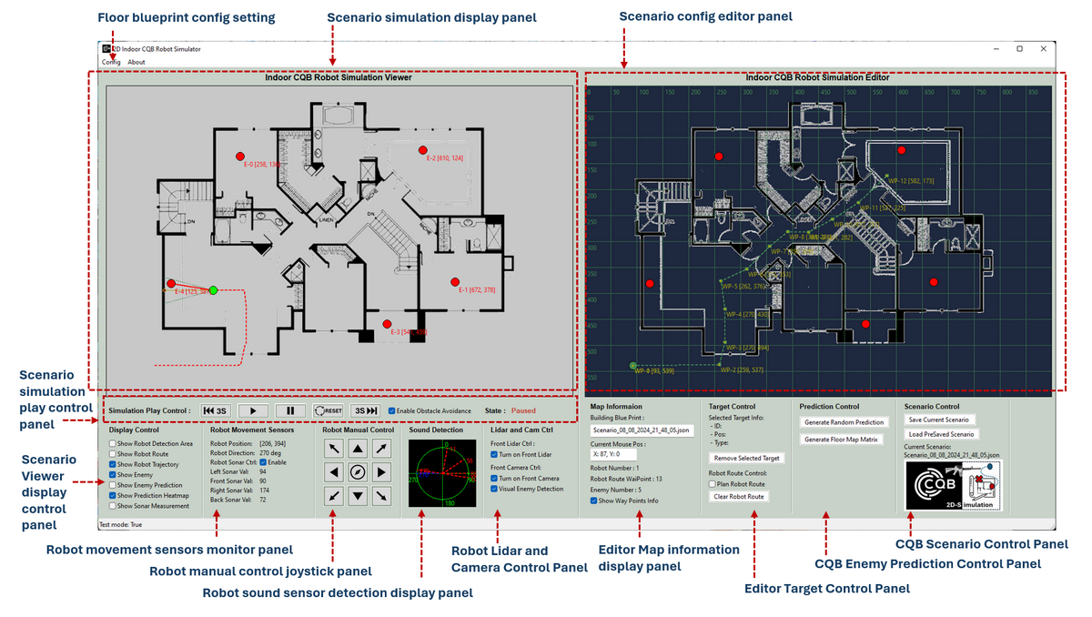
Figure-09: Program UI introduction, version v0.1.2 (2024)
Each panel has a specific function:
-
Scenario Simulation Display Panel: Displays the current scenario simulation animation, including robot position, enemy detection, and prediction states.
-
Scenario Simulation Play Control Panel: Functions like a video player, allowing you to play, pause, and step through the simulation both forward and backward.
-
Scenario Viewer Display Control Panel: Provides options to toggle various components on the viewer panel, such as displaying the robot's path.
-
Robot Movement Sensors Monitor Panel: Shows real-time data from the UWB position sensor, compass, and sonar.
-
Robot Manual Control Joystick Panel: Allows manual control of the robot's movement direction and the ability to return to the last waypoint.
-
Robot Sound Sensor Detection Display Panel: Displays possible enemy sound directions detected by the sound sensors.
-
Robot LIDAR and Camera Control Panel: Controls the LIDAR, camera, and enemy detection functions, allowing you to toggle them on or off.
-
Editor Map Information Display Panel: Displays information about the editor map, including mouse position, blueprint file name, enemy count, and the number of waypoints in the robot's path.
-
Editor Target Control Panel: Displays information about the selected target and provides controls for editing the AP path.
-
CQB Enemy Prediction Control Panel: Allows adjustment of enemy prediction parameters and configuration of the map matrix.
-
CQB Scenario Control Panel: Enables you to save the current scenario to a file or load a previously saved scenario.
Reference
- Project Link: https://github.com/LiuYuancheng/2D_Indoor_CQB_Simulator
-
SWAT tactical robot – DOGO: https://bssholland.com/product/swat-tactical-robot-dogo/
-
Ultra Wide-Band (UWB) Indoor Positioning System Technology : https://mapsted.com/indoor-location-technologies/uwb-positioning
last edit by LiuYuancheng (liu_yuan_cheng@hotmail.com) by 10/08/2024 if you have any problem, please send me a message.
